How It Works
Magnetic Fuel Conditioning
Eco-Clamp™ applies a rotational magnetic flux field to the fuel stream just before combustion. The helical alternating N–S magnet array realigns hydrocarbon chains for finer atomization, charges hydrogen and oxygen molecules for cleaner oxidation, and reduces carbon deposit formation in burners and heat exchangers.
The result is a more stable, high-temperature, low-emission flame — and more complete combustion from the same volume of fuel.
No wiring, no power source, and no modification to the fuel-delivery system. Eco-Clamp™ installs externally on the existing fuel line and begins working immediately.
- Molecular Realignment — aligns hydrocarbon chains for finer atomization
- Ionization Effect — charges hydrogen/oxygen molecules for cleaner oxidation
- Carbon Deposit Reduction — minimizes fouling in burners and heat exchangers
- Improved Air–Fuel Mix — produces a stable, high-temperature, low-emission flame
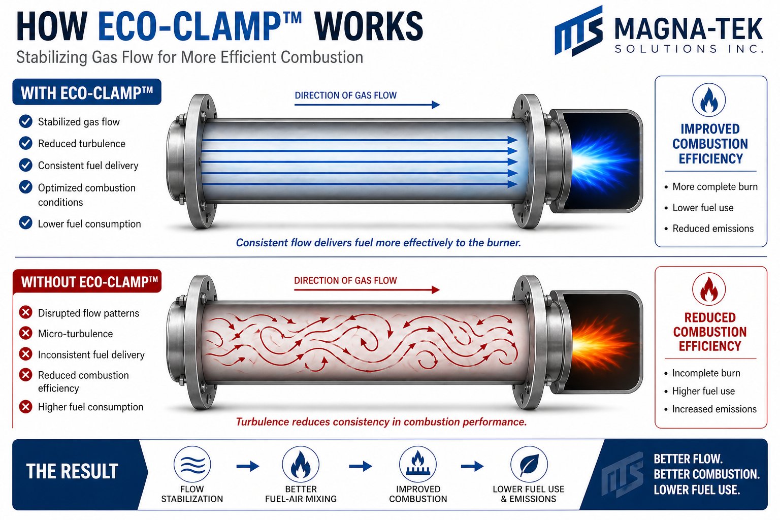
How Eco-Clamp™ Works
Stabilizing Gas Flow for More Efficient Combustion
Without conditioning, fuel arrives at the burner with disrupted flow and micro-turbulence — inconsistent delivery that reduces combustion efficiency. Eco-Clamp™ stabilizes gas flow before it reaches the burner, producing a more consistent, complete burn.
Independent Validation
ASHRAE-Protocol Laboratory Testing
ONspex Laboratories (Cleveland, OH) tested Eco-Clamp™ per ASHRAE 103-1993 on a Luxair 90% up-flow furnace, comparing combustion performance with and without the device installed.
| Condition | Combustion Efficiency | CO₂ (%) | CO (ppm) | Δ Temp Rise (°F) |
|---|---|---|---|---|
| Without Eco-Clamp™ | 89.55% | 6.6 | 8 | 50 |
| With Eco-Clamp™ | 90.97% (+1.42%) | 7.3 | 0 | 52.5 |
Results: complete CO elimination, higher heat output, and improved combustion stability under controlled lab conditions.
At a multi-family site in Skyview, Alberta, a 60-day pre/post weather-normalized regression analysis (R² ≥ 0.80 confidence threshold) confirmed a 16.78% verified reduction in natural gas consumption following Eco-Clamp™ installation — with post-installation usage consistently plotting below the baseline trend line across the full outdoor temperature range tested.
Verified Performance
What the Data Shows
Fuel Efficiency
Up to 20% improvement, typically 5–17% depending on system conditions, fuel type, and equipment age.
Emissions Reduction
CO down 60–80%, unburned hydrocarbons (HC) down 80–90%, NOx down approximately 20%.
Return on Investment
Typical payback of 6–18 months, depending on load profile and runtime hours.
CO₂ Reduction
Up to 15% per site — supports Scope 1 emissions reduction reporting.
Equipment Longevity
Reduced fouling and carbon buildup extend service intervals and equipment life — >20 year magnet service life with no flux loss.
Maintenance
None required. Passive operation with zero moving parts — only an annual ~5-minute visual check is recommended.
Sizing
Typical Applications & Recommended Models
Model selection is based primarily on pipe size and confirmed BTU input. Custom assemblies are available for pipe diameters to 8″ and thermal loads above 9 million BTU/h.
| Equipment Type | BTU Range | Pipe Size | Recommended Model |
|---|---|---|---|
| Residential / Commercial HVAC | 1k – 120k | ¼″ – ½″ | AFS-LD / AFS-HD |
| Rooftop MUA / Unit Heaters | 250k – 600k | 1″ – 1¾″ | AFS-1 / AFS-1A |
| Boilers / DHW Systems | 600k – 3MM | 1½″ – 3″ | AFS-1A / AFS-2 |
| Industrial Burners / Generators | 3MM – 9MM | 3″ – 8″ | AFS-2 – AFS-8 (Custom) |
Logical Relations
Eco-Clamp™ + AquaMagna™ — Pairing Fuel & Water Treatment
The same equipment that burns fuel often relies on water nearby — a boiler's flame and its feedwater, an HVAC unit's gas burner and its condenser loop. When BTU input and pipe size point to a given Eco-Clamp™ model, the equipment type typically has a corresponding AquaMagna™ application worth assessing at the same time.
| Eco-Clamp™ Equipment Bracket | Corresponding AquaMagna™ Application | Why They're Paired | |
|---|---|---|---|
| AFS-LD / AFS-HD Residential/Commercial HVAC 1k–120k BTU |
↔ | Domestic Hot Water Lines | Small gas appliances of this size are typically paired with small domestic water heaters — both benefit from conditioning at this scale. |
| AFS-1 / AFS-1A Rooftop MUA / Unit Heaters 250k–600k BTU |
↔ | Chillers & HVAC Systems | Rooftop gas units are usually integrated with building HVAC water loops — chillers, condensers, and fan coil supply lines. |
| AFS-1A / AFS-2 Boilers / DHW Systems 600k–3MM BTU |
↔ | Boilers & Steam Systems | A direct match — the same boiler needs fuel-side conditioning for combustion efficiency and water-side conditioning to prevent scale on heat exchange surfaces. |
| AFS-2 – AFS-8 Industrial Burners / Generators 3MM–9MM BTU |
↔ | Food Processing & Beverage Lines / Equipment Prone to Scale, Rust, or Sediment | Large industrial burners and generators run alongside high-volume process water and cooling systems facing the same scale and fouling pressures. |
Installation & Compliance
Simple Retrofit. Code-Compatible.
Installation Guidelines
- Ensure the pipe surface is clean and free of oil and debris before installation
- Position the clamp as close as practical to the burner or manifold connection — typically 12–36 inches
- Install on a straight pipe section; avoid elbows, fittings, motors, and strong magnetic fields
- Secure the halves evenly using the supplied fasteners; do not overtighten
Code Compatibility
Eco-Clamp™ installs externally and does not alter or penetrate the gas system or appliance connection. It does not require certification under CSA B149.1 (Canada) or NFPA 54 / ANSI Z223.1 (U.S.) and is fully compatible with these codes when installed per standard fuel-system safety practices.
ESG & Energy Program Alignment
Recognized as a passive, non-intrusive fuel-efficiency measure suitable for custom incentive review under NRCan's Greener Buildings Initiative, IESO Save-on-Energy Custom Programs (Ontario), and the U.S. DOE Better Buildings Challenge.
Technical Specifications
Eco-Clamp™ Specifications
| Parameter | Specification | Notes |
|---|---|---|
| Magnetic Field Intensity | 10,000 – 12,500 Gauss | NdFeB N42 or Ceramic Grade 5–8 |
| Field Geometry | Helical alternating N–S array | Per U.S. Patent 9,305,692 B2 |
| Housing | Aluminum alloy body, PVC-coated | — |
| Fasteners | Stainless A2 / A4 | Non-magnetic |
| Operating Temperature | −40°C to +200°C | Continuous |
| Service Life | > 20 years | No flux loss |
| Maintenance | None required | Passive operation |
Calculate Your Fuel Savings
Use our interactive Eco-Clamp™ estimator or request a formal ROI projection.